 Surveying & Architects A unique platform of Civil Engineering
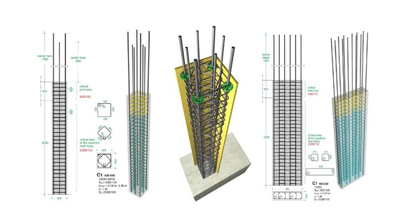
Column Reinforcement Detail | Lateral Reinforcement for Columns | Steel Reinforcement
Reinforcement Details for Columns:
Offset Bars: Offset bent longitudinal bars shall conform to the following:
- The maximum slope of an inclined portion of an offset bar with the axis of the column shall not exceed 1 in 6.
- Portions of the bar above and below an offset shall be parallel to the axis of the column.
Horizontal support at offset bends shall be provided by lateral ties, spirals, or parts of the floor construction. Horizontal support provided shall be designed to resist 1.5 times the horizontal component of the computed force in the inclined portion of the offset bars. Lateral ties or spirals, if used, shall be placed not more than 150 mm away from points of the bend. - Offset bars shall be bent before placement in the forms (see the table below). Where the face of the column above is offset 75 mm or more from the face of the column below, longitudinal bars shall not be permitted to be offset bent. The longitudinal bars adjacent to the offset column faces shall be lap spliced using separate dowels.
Steel Cores: Load transfer in structural steel cores of composite compression members shall be provided by the following:
- Ends of structural steel cores shall be accurately finished to bear at the end bearing splices, with positive provision for alignment of one core above the other in concentric contact.
- At end bearing splices, bearing shall be considered effective to transfer not more than 50 percent of the total compressive stress in the steel core.
- The base of structural steel section shall be designed to transfer the total load from the entire composite member to the footing; or, the base shall be designed to transfer the load from the steel core only, provided ample concrete section is available for the transfer of the portion of the total load carried by the reinforced concrete section to the footing by compression in the concrete and by reinforcement.
Learn More
What is Sprayed Concrete in Concrete Construction
Lateral Reinforcement for Columns:
Spirals: Spiral reinforcement for columns shall conform to the following:
(a) Spirals shall consist of evenly spaced continuous bar or wire of such size and so assembled as to permit handling and placing without distortion from designed dimensions.
(b) The size of spirals shall not be less than 10 mm diameter for cast‐in‐place construction.
(c) The minimum and maximum clear spacing between spirals shall be 25 mm and 75 mm respectively.
(d) Anchorage of spiral reinforcement shall be provided by 1.5 extra turns of spiral bar or wire at each end of a spiral unit.
(e) Splices in spiral reinforcement shall be lap splices of 48 spiral diameter for deformed uncoated bar or wire and 72 spiral diameter for other cases, but not less than 300 mm.
(f) Spirals shall extend from the top of footing or slab in any story to the level of the lowest horizontal reinforcement in members supported above.
(g) Spirals shall extend above the termination of the spiral to the bottom of the slab or drop panel, where beams or brackets do not frame into all sides of a column.
(h) Spirals shall extend to a level at which the diameter or width of capital is 2 times that of the column, in case of columns with capitals.
(i) Spirals shall be held firmly in place and true to line.
Learn More
Bar Bending Schedule B.B.S
Thumb Rules For Civil Engineers In Building Construction
Ties: Tie reinforcement for compression members shall conform to the following:
(a) All bars shall be enclosed by lateral ties, at least 10 mm φ in size for longitudinal bars 32 mm φ or smaller, and at least 12 mm φ in size for 36 mm φ to 57 mm φ and bundled longitudinal bars.
(b) Vertical spacing of ties shall not exceed 16 longitudinal bar diameters or 48 tie diameters, or the least dimension of the compression members.
(c) Ties shall be arranged such that every corner and alternate longitudinal bar shall have lateral support provided by the corner of a tie with an included angle not more than 135 deg. No vertical bar shall be farther than 150 mm clear on each side along with the tie from such a laterally supported bar. Where longitudinal bars are located around the perimeter of a circle, a complete circular tie is allowed.
(d) The lowest tie in any story shall be placed within one‐half of the required tie spacing from the topmost horizontal reinforcement in the slab or footing below. The uppermost tie in any story shall be within one‐half of the required tie spacing from the lowest horizontal reinforcement in the slab or drop panel above.
(e) Where beams or brackets provide concrete confinement at the top of the column on all (four) sides, the top tie shall be within 75 mm of the lowest horizontal reinforcement in the shallowest of such beams or brackets.
(f) Where anchor bolts are placed in the top of columns or pedestals, the bolts shall be enclosed by lateral reinforcement that also surrounds at least four vertical bars of the column or pedestal. The lateral reinforcement shall be distributed within 125 mm of the top of the column or pedestal, and shall consist of at least two 12 mm φ bars or three 10 mm φ bars.
(g) Where longitudinal bars are arranged in a circular pattern, individual circular ties per specified spacing may be used.
Other Post.
-
How to calculate the number of bricks in 1 CFT wall
-
Types of Stone Masonry
-
What Is Difference Between Pre-tension And Post-tension
-
How Many Types Of Septic Tanks Based On Materials
-
How To Estimate Per Meter Weight Of Reinforcing Steel Bar
-
How To Calculate The Cutting Length Of Circular Stirrup