 Surveying & Architects A unique platform of Civil Engineering
How to Calculate Staircase Concrete & Bar Bending Schedule And Staircase Reinforcement Details

stair rise and run calculator
Calculation of Staircase Three Different Parts as Below
1. Concrete Calculation for Staircase
2. Bar Bending Schedule for Staircase
First, start the calculation of staircase sum basic knowledge of staircase
Learn More
How To Calculate The Height Of Any Buildings And An Objects Using With Theodolite
Most Important Point In This Article
A various part of Stair
Step
• A flat surface, especially one in a series, on which to place one’s foot when moving from one level to another. all step is composed of tread and riser.
Tread
• Tread is a scrap of the stairway that’s stepped in. It’s the top or flat surface to press beneath the feet.
• It’s trodden on while climbing or descending the staircase.
• It’s constructed to the same thickness as another floor. There’s always one fewer tread than risers at stairs.
• The general horizontal distance of the stairs is going to be the number of threads added together.
• The horizontal projection of a step in a staircase is called tread. It is also known as going
• In residential buildings, the tread length provided is 250 mm while in public buildings maximum length 270 mm to 300 mm.
Riser
• This riser is the vertical portion between each tread on the stair.
• Not all stairs have risers. The rise-less steps are called the open thread.
• Open riser stairs have grown in popularity Recently years. Closed tread stair has risers included.
• This vertical board forms the face of the step, also forms the space between one step and the next.
• Rise provided could be uniform. It is normally hight 150 mm to 175 mm in residential buildings while it is kept between hight 120 mm to 150 mm in public buildings.
• However, in commercial buildings, more rise is provided from the consideration of the economic floor area.
Nosing
• Nosing is the flat protruding edge of a stair at which most foot traffic occurs.
• Mostly, it’s the half curved molding fixed into the ends of those threads exposed at a half that covers where the balusters fit into the treads.
• Nosing is the border of the tread projecting beyond the face of the riser and the face of a cut string. This is the place where the thread above a riser overhangs it. Sometimes, the tread may not have a nosing.
Base Rail or Shoe Rail
• For systems in which the baluster doesn’t start at the treads, they go to a base rail. This allows for identical balusters, avoiding this second baluster problem.
Landing
• This is a platform provided between two flights.
1. Concrete Calculation for Staircase
Concrete calculation
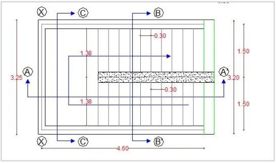
Section 1
Landing area concrete = L x B x H
Landing area concrete = 1.7 M. x 3.25 M. x 0.150 M.
Landing area concrete = 0.830 Cu.m.——–(1)
Section 2
Waist slab area concrete = L x B x H x N
Waist slab area concrete = 3.85 M. x 1.5 m. x 0.150 M. x 2 Nos.
Waist slab area concrete = 1.732 Cu.m. ——–(2)
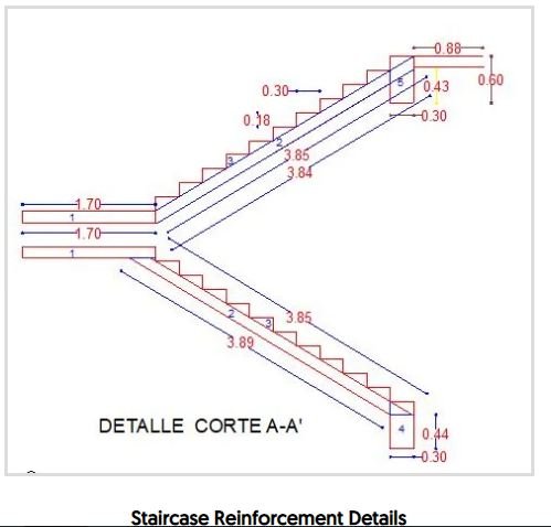
Section 3
Steps area concrete = L x Vloume of trianglar area x N x Q
Steps area concrete = 1.5 M. x( 0.300 M. x 0.150 M x (1/2)) x 2 Nos. X 11 Qty
Steps area concrete = 0. 75 Cu.m. ——–(3)
Section 4
Beam area concrete = L x B x H X N
Beam area concrete = 1.5 M. x 0.44 M. x 0.300 M. x 2 Nos.
Landing area concrete =0.400 Cu.m.——–(4)
Total Concrete of Staircase = (1) + (2) + (3) + (4)
Total Concrete of Staircase = 0.830 Cu.m. + 1.732 Cu.m. + 0. 75 Cu.m. + 0.400 Cu.m.
Total Concrete of Staircase = 3.712 Cu.m.
2. Bar Bending Schedule for Staircase
Section 1
Landing Area Bar Bending Schedule
Distribution bar 8 mm C/C 120 mm Length 3.25 in Y-axis Distribution area 1.5m
So No, of 8 mm Steel bar = 1.5 M. / 0.120 M. = 12.5 Nos
Consider 13 Nos. steel bar use Top Side +13 Nos Steel use Bottom Side
Weight of distribution of 8 mm dia steel bar = L x Nos of steel x Weight of Steel
Weight of distribution of 8 mm dia steel bar = 3.25 x 13 x 2 x 0.395 (0.395 kg/m is 8mm dia steel bar weight)
Weight of distribution of 8 mm dia steel bar = 33.34 kg ——– (1)
Section 1 Total = 33.34 kg
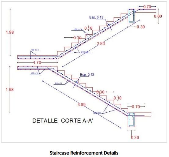
Section 2-1
Wasit slab Bar Bending Schedule
Distribution bar 8 mm C/C 140 mm Length 1.5 in Y-axis Distribution area 3.89m
So No, of 8 mm Steel bar = 3.89 M. / 0.140 M. = 27.75 Nos
Consider 28 Nos. steel bar use Top Side +28 Nos Steel use Bottom Side
Weight of distribution of 8 mm dia steel bar = L x Nos of steel x Weight of Steel
Weight of distribution of 8 mm dia steel bar = 1.5 x 28 x 2 x 0.395 (0.395 kg/m is 8mm dia steel bar weight)
Weight of distribution of 8 mm dia steel bar = 33.1 kg ——– (2-1-1)
Main bar Bottom Area 10mm dia C/c 80 mm distance
Length of main bar bottom area = 1.5 M. – 0.180 M. + 0.150 M. + 3.89 M. + 0.450 M.
Length of main bar bottom area = 5.81 m
Nos of bar 10 mm dia C/c 80 mm distance = 1.5 M. / 0.080 M. = 18.75 Nos.
Consider 19 Nos. steel bar use Bottom bar Side
Main bar Bottom Area 10mm dia steel bar = 5.81 M. X 19 Nos. X 0.617 kg/m (0.617 kg/m is 10mm dia steel bar weight)
Main bar Bottom Area 10mm dia steel bar = 68.11 kg ——– (2-1-2)
Other Post
The Role And Responsibilities Of Quantity Surveyor In Current Construction Sectors
Main bar Top Area 10mm dia C/c 80 mm distance
Length of main bar top area = 1.7 M. – 0.180 M. + 3.89 M. + 0.450 M. +0.250 M.
Length of main bar top area = 6.11 m
Nos of bar 10 mm dia C/c 80 mm distance = 1.5 M. / 0.080 M. = 18.75 Nos.
Consider 19 Nos. steel bar use Bottom bar Side
Main bar Top Area 10mm dia steel bar = 6.11 M. X 19 Nos. X 0.617 kg/m (0.617 kg/m is 10mm dia steel bar weight)
Main bar Bottom Area 10mm dia steel bar = 71.63 kg ——– (2-1-3)
Section 2-1 total = 33.1 kg + 68.11 kg + 71.63 kg = 172.84 kg
Section 2-2
Waist slab Bar Bending Schedule
Distribution bar 8 mm C/C 140 mm Length 1.5 in Y-axis Distribution area 3.83m
So No, of 8 mm Steel bar = 3.83 M. / 0.140 M. = 27.75 Nos
Consider 28 Nos. steel bar use Top Side +28 Nos Steel use Bottom Side
Weight of distribution of 8 mm dia steel bar = L x Nos of steel x Weight of Steel
Weight of distribution of 8 mm dia steel bar = 1.5 x 28 x 2 x 0.395 (0.395 kg/m is 8mm dia steel bar weight)
Weight of distribution of 8 mm dia steel bar = 33.1 kg ——– (2-2-1)
Main bar Bottom Area 10mm dia C/c 80 mm distance
Length of main bar bottom area = 1.5 M. – 0.180 M. + 0.150 M. + 3.83 M. + 0.450 M.
Length of main bar bottom area = 5.78 m
Nos of bar 10 mm dia C/c 80 mm distance = 1.5 M. / 0.080 M. = 18.75 Nos.
Consider 19 Nos. steel bar use Bottom bar Side
Main bar Bottom Area 10mm dia steel bar = 5.78 M. X 19 Nos. X 0.617 kg/m (0.617 kg/m is 10mm dia steel bar weight)
Main bar Bottom Area 10mm dia steel bar = 67.75 kg ——– (2-2-2)
Main bar Top Area 10mm dia C/c 80 mm distance
Length of main bar top area = 1.7 M. – 0.180 M. + 3.83 M. + 0.450 M. +0.250 M.
Length of main bar top area = 6.05m
Nos of bar 10 mm dia C/c 80 mm distance = 1.5 M. / 0.080 M. = 18.75 Nos.
Consider 19 Nos. steel bar use Bottom bar Side
Main bar Top Area 10mm dia steel bar = 6.05 M. X 19 Nos. X 0.617 kg/m (0.617 kg/m is 10mm dia steel bar weight)
Main bar Bottom Area 10mm dia steel bar = 70.92 kg ——– (2-2-3)
Section 2-2 Total = 31.1 kg + 68.09 kg +70.92 kg = 170.11 kg
Total Section 2 weight = 172.84 kg + 170.11 kg = 342.95 kg
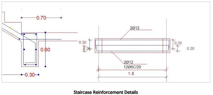
Section 3
Beam area bar bending schedule
8mm dia Ring Size for length of column ring = Column Size – Cover
Ring Size for length of column ring = ( L of Column – cover – cover + B of Column – cover – cover + Hook ) x 2
Ring Size for length of column ring = (600 -25 -25 + 300 – 25 -25 +8 ) x 2
8mm dia Ring Size for lenth of column ring = 1.616 M.
No ring requirement = Length / Spacing
No ring requirement = 1.5 /0.140 = 11 Nos
Weight of ring = 1.616 x 11 x 0.395 = 7.02 kg ——–(3-1)
Length of Bar = Length of bar +( wall bering + wall bering ) + ( End side L Bend x No of Qty )
12 mm dia Length of Bar = 1.5 + (0.200 + 0. 200 ) + (0. 300 X 4)
Length of Bar = 3.1 M.
Weight of ring Main bar = 3.1 x 6 x 0.89 = 16.554 kg ——–(3-2) (0.89 kg/m is 12mm dia steel bar weight)
Section 3 total = 7.02 kg + 16.554 kg = 23.57 kg x 2 ( Because of same two beam ) = 47.51 kg
Total Weight of Staircase Bar Bending schedule
= Section 1 + Section 2 + Section 3
= 33.34 kg + 342.95 kg + 47.51 kg
Total Weight of Staircase Bar Bending schedule = 423.79 kg
Learn More
What is Scale Factor
To get more information, Visit Our Official website
Land Surveying & Architects
JOIN US & LIKE OUR OFFICIAL FACEBOOK PAGE
THANKS.

3 comments
Pingback: Steel Calculation For Circular Slab - Surveying & Architects
Pingback: how to calculate the weight of different types of steel - Surveying & Architects
Pingback: How To Calculate The Cutting Length Of Circular Stirrup - Surveying & Architects