 Surveying & Architects A unique platform of Civil Engineering
How to Use Pile Load Test Data to Design Pile Foundations
An expensive but very dependable option to find out the load capacity of a pile is the Pile Load Test. It is not the cheapest option, yes, but if your pocket has that kind of load bearing capacity, we say you go for it ? because you can’t find a better solution to the issue of finding how much your pile can take.
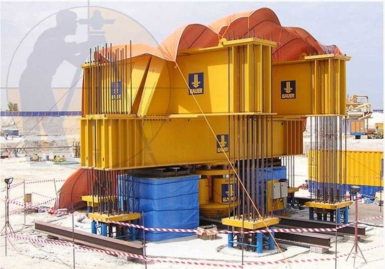
This sort of load testing is performed on-site, live, on test piles you’ve built there. The design capacity of the pile is clearly indicated by this test. The test itself is straightforward ? put enough weight on the pile and see how much it flattens. Keep applying more load on the test pile incrementally and measure its settlement, seems simple enough.
You can jack up dead loads on the pile, or use beams to uplift anchor piles to supply reaction for the jack. You can either use the Constant Rate of Penetration (CRP) or Maintained Load (ML) test to gauge the settlement data.
When would you know that the pile has had enough and the load can’t be considered safe anymore for that pile? Well, the engineering community is still divided about it. Terzaghi (1942) said if the pile settles by 10% of its own diameter, the load causing that is the failure load. However, the German DIN 4026 says when the pile has undergone irreversible settlement of at least 2.5% of its own dia, then that’s the max load for that pile.
CP 2004 provides a very confusing but probably the most scientifically perfect definition of a failure load. It focuses more on the rate of settlement rather than the amount of it. According to CP 2004, the load which causes the rate of settlement continue undiminished without further increase increment of load (unless this rate is so slow as to indicate that this settlement may be due to consolidation of the soil) is the failure load. Needless to say, it’s a tiny bit difficult to conceive of, let alone apply in the field. Most people just go by the old standard.
Let us now take a real-life pile design problem and try to solve it.
Data given
We have three piles, and we need to determine which one to use in our structure. We have:
- Permanent load Gk = 3600 KN
- Variable Load Qk = 1740 KN
- Pile dia = 750 mm
- Pile length = 15 meters
Let’s say we carried out Pile Load Tests on all three piles, and plotted the following graph from the results. We went by the Terzaghi definition as it’s the most commonly used, you know why.
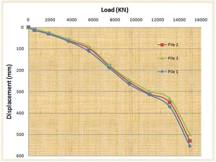
Now, we will try to figure out which pile to use utilizing the above data.
Solution
The ultimate resistance of the pile is the load at settlement of 10% of the pile diameter.
Settlement = 750 ? (10/100)
= 75mm
From the load settlement graph for each pile:
- Pile 1 Rm= 4156.25 KN
- Pile 2 Rm= 4318.325 KN
- Pile 3 Rm= 4887.8 KN
The mean and minimum measured pile resistances are;
- Rm,mean= 4454.125 KN
- Rm,min= 4156.25 KN
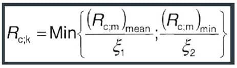
The characteristic pile resistance is-obtained by-dividing the mean and minimum measured pile resistances by the correlation factors ξ1 and ξ2 and choosing the minimum value. The equation below is given by equation 7.2 of Euro-code 7.
For 3 number of test piles (Table A9, EC7);
- ?1= 1.20
- ?1= 1.05
- Rc,k=min {4454.125/1.2, 4156.25/1.05} = 3711.77 KN
learn More
Civil Site Engineer Must Know +18 Civil Engineer Tips And Trick
Design Approach 1
Combinations of sets of partial factors
- DA1.C1 ? A1 + M1 + R1
- DA1.C2 ? A2 + M1 or M2 + R4
Partial factors for actions;
- A1?G= 1.35?Q= 1.5
- A2?G= 1.0?Q= 1.30
Partial factors for materials
M1 and M2 not relevant (??’ = 1.0, not used)
Partial Resistance factors
- R1?t= 1.15 (Total/combined compression)
- R4?t= 1.5
DA1.C1Fc,d= 1.35Gk + 1.5Qk
= (1.35 ? 3600) + (1.5 ? 1740)
= 7470 KN
DA1.C2Fc,d= 1.0Gk + 1.3Qk
= (1.0 ? 3600) + (1.3 ? 1740)
= 5862 KN
For a single pile;
DA1.C1Rc,d=Rc,k/?t
= 3711.77/1.15
= 3227.62 KN
DA1.C2Rc,d=Rc,k/?t
= 3711.77/1.5
= 2474.513 KN
Assuming no pile group effect, for n piles,
Resistance = n ?Rc,d
Hence,
DA1.C1 n ≥Fc,d/Rc,d
= 7470/3227.62
= 2.31
DA1.C2 n ≥Fc,d/Rc,d
= 5862/2474.513
= 2.36
Therefore, DA1.C2 controls, and 3 number of piles will be required.
Therefore
- Rc,d= 3 ? 2474.513 = 7423.539
- Fc,d= 5862 KN
- Fc,d/Rc,d= 5862/7423.539
= 0.789 < 1.0(Ok)
learn More
Checklist For R.C.C Slab & Beams
Design Approach 2
Combinations of sets of partial factors
DA2 A1 + M1 + R2
Partial factors for actions;
A1?G= 1.35?Q= 1.5
Partial factors for materials
M1 not relevant (??’ = 1.0, not used)
Partial Resistance factors
R2?t= 1.1 (Total/combined compression)
Fc,d= 1.35Gk + 1.5Qk
= (1.35 ? 3600) + (1.5 ? 1740)
= 7470 KN
For a single pile;
Rc,d=Rc,k/?t
= 3711.77/1.1
= 3374.336 KN
Assuming no pile group effect, for n piles,
Resistance = n ?Rc,d
Hence,
n ≥Fc,d/Rc,d
= 7470/3374.336
= 2.21
Therefore, the number of piles required = 3 piles
Design Approach 3
Combinations of sets of partial factors
DA3 A1 + M1 + R3
Partial Resistance factors
R3?t= 1.0 (Total/combined compression)
Since the R3 recommended partial resistance factor is 1.0, there is no margin for safety on the resistance provided. Therefore, this cannot be used for the design.
Conclusion
3 Number of 750mm diameter piles is suitable for the load at ultimate limit state.