 Surveying & Architects A unique platform of Civil Engineering
Contour Mapping – Characteristics, Methods & Uses.
The Contour are the lines joining the points of equal elevation on the surface of earth or we can say that the contour is a line in which the ground surface is intersected by the level surface obtained by joining points of the equal elevation.

Contour Map.
The map on which contour lines are plotted are known as the contour map.
The Contour map gives an idea of the altitudes of the surface features as well as their relative positions in the plan serves the purpose of the plan as well as section.
Contouring.
The process of the tracing lines on the surface of the earth is called contouring.
Contour Interval.
The constant vertical distance or the difference in the level between 2 consecutive contours in the map is called contour interval.
Horizontal Equivalent.
The horizontal distance between any 2 consecutive contours is called as the horizontal equivalent.
The contour interval is unchanged or constant between the consecutive contours while the horizontal equivalent is the variable & depends upon the slope of the earth surface.
Contour Gradient.
The line laying on the ground which maintains the constant inclination to the horizontal is known as contour gradient. It is measured out by an instrument is called Clinometer.
Learn More
-
How to calculate The gradient, run and rise in civil construction
-
How To Calculate The Asphalt Quantity For Road Work
Characteristics of Contour.
- The Contour lines always form the closed loops, however they may close either on the map itself or outside map.
- The Contours are always perpendicular to the direction of the steepest slope.
- All points in the contour line have the same elevation.
- For the given contour interval, scale of the map & the nature of the terrain decide the horizontal equivalent. As the slope becomes more & more steeper, the horizontal equivalent decreases.
- If the contours are parallel & the horizontal difference between 2 consecutive contour is constant for the map, than the contour shows uniform slope.
- Straight, parallel and the equally spaced contour lines represent the plane surface.
- The Irregular contours represents rough terrain.
- For depressions, the contour value is decreasing from the outside towards center.

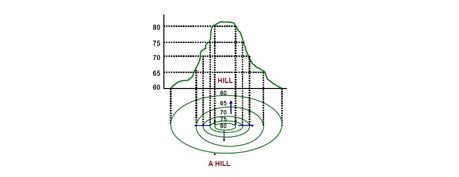
- For the hill contour mapping, the contour value is increasing from outside towards center.
- The Contour lines cross the ridge at right angles. If the higher values are inside the bend or loop in the contour, it indicates the ridge.

- The Contour lines cross the valley at right angles. If the higher values are outside the bend, it represents the valley.

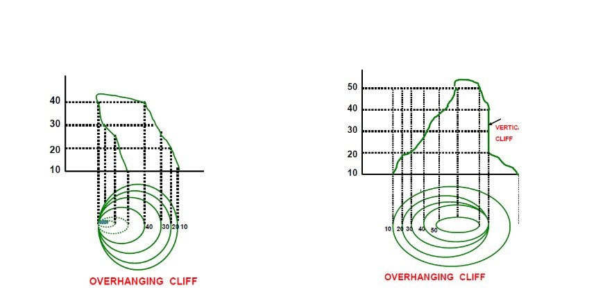
- 2 contours of different elevation neither cross each other nor joins. However, in the special case of an overhanging cliff or the cave penetrating the hill inside, the contours appear to cross each other.
Methods of The Contouring
There are mainly 2 methods of locating contours.
1. Direct Method of the Contouring.
2. Indirect Method of the Contouring.
1. Direct Method of the Contouring.
In this method, the contour to be plotted is actually traced on ground by locating the points of that elevation. The horizontal position of the points so located is then determined & plotted on the plan. The pegs of the different contours are coded so that 1 set cannot be mistaken for the other.

- This is more accurate method than the indirect methods as the points are located directly & in generally used for the small areas.
- The main disadvantage of this method is that the method is slow and the cumbersome and is not suitable for the contouring large areas.
Learn More
2. Indirect Method of the Contouring.
In this method the points located and the surveyed are not necessarily on the contour lines but the spot levels are taken at some selected points called as guide points & the levels of points are determined. The horizontal positions of these points are then determined and the points are plotted on the plan. Their positions are then plotted on the plan & the contours drawn by interpolation.
This method of the contouring is also known as contouring by spot levels. The indirect method is more convenient than the direct method & is suitable for the contouring large areas.
There are mainly 3 method of the contouring in indirect method.
a) – Grid Method or Square Method.
This method is used for the surveying of the small to medium areas and for the less undulated land.
- The area to be surveyed is divided into the number of squares, the size of the squares depends on the nature of the ground and the contour interval. Usually it varies from five – m to 30 m.
- From the elevations of the grid points, the points on the various contours are located by the interpolation.
b) – Cross Section Method.
This method is the most suitable for the surveys of long narrow strip such as a road, railway or canal etc.
- The Cross sections are located on the ground at the right angles to the fixed line or center line of the route. The cross section lines need not necessarily be at right angles to the center line of work. This may be inclined at any angle to the center lines of cross section.
- Depending on the nature of the ground and the contour spacing, the spacing of the cross sections is decided.
- The common value is twenty to 30 m in the hilly country and hundred m in the flat country.
- The levels of the points along the section lines are plotted on the plan and contours are then interpolated as usual.
Learn More
-
Linear measurements in the surveying by Direct Method
-
What is the Benefits and Drawbacks of Total Station
-
What is drone Surveying and benefits of the drone Surveying
c) – Radial Lines Method.
This method is the particularly useful for contouring small hilly areas where radial lines are drawn from the peak to cover the entire area.
- The Grid points are taken on the radial lines & their elevations are determined.
- The contour lines are drawn through the interpolation.
d) – Controlling Point Method.
Here the elevations are determined for the few selected key or controlling points. The contour lines are then drawn through interpolation.
- This is however an approximate but the quick method.
- For fairly uniform sloping ground, this method gives quite the good results.
Uses of the Contour Maps.
There are lots of the uses of contour maps as the contour survey is carried out at the starting of the any engineering project such as a roadway, railway, canal, dam and building etc. Some of the major uses are as follows.
- For the assessment of the terrain character.
- Used to select the most economical or suitable site.
- To locate the alignment of the canal so that it should follow a ridge line.
- To mark the alignment of the roads and railways so that the quantity of the earthwork should be minimum.
- Used for the assessment of the catchment area and volume.
- To trace out the given grade of the particular route.
Other Post
-
Types Of Curves In Surveying Work
-
How to calculate the RL of temporary benchmark on the site
-
Rise and fall method with Examples